X-RAY INSPECTION
onventional top-down (2D) X-ray systems are inadequate to detect many common BGA defects. Given the widespread use of BGA, flip-chip, and leadless devices, the ability to fixture and manipulate a sample with flexibility is no longer optional. Circuit assemblers need more than just top-down visibility for inspection and validation.
Nikon Metrology Partner
PSI's three Nikon 160kV X-ray stations answer the challenge. Offering real-time, off-axis X-ray, these systems are designed specifically for inspection of PCBAs and array devices, whether on production lines or in failure analysis laboratories. Samples can be manipulated with a 360 degree rotational axis, and up to 75 degree oblique viewing angle, while intuitive software allows operators to visualize the most demanding defects. PSI operates two Nikon (formerly X-Tek) Revolution systems, and a newer Nikon XTV-160 system.
Real-time examples
|
In this video are three separate X-ray inspections of BGA's, each revealing a distinctive solder joint defect called "head-in-pillow," so named for its resemblance to a head resting on a pillow. The defect is usually easy to spot using off-axis X-ray. 'Head-in-pillow' (HiP) defects occur under BGA devices when the solder sphere and the paste underneath it do not flow together, that is, they fail to bond chemically and mechanically. Direct causes of HiP fall into two basic categories, either the solder ball and paste are not in contact at the time of reflow, or there is insufficient flux activity to overcome surface oxides. (Or both.) Lack of physical contact might be due to alignment problems, lack of coplanarity of board or part, or variation in solder volume. Insufficient flux activity might be due to improper storing or handling of paste, too long a reflow profile, or excessive oxidation. And in turn, each of these problems can have multiple underlying causes. |
|
In this video, one solitary sphere has failed to form a bond with the pad at the board interface. The defect comes into focus at about the 0:19 mark. Notice how the solder sphere in the center of the screen is round, whereas all of its neighbors have a gumdrop shape. Two factors contribute to the general shape of these spheres, 1) there is warping of either board or part, increasing the stand-off height, and 2) the pads on the board are wider than the pads on the part. Nothwithstanding their atypical gumdrop shape, all these joints are properly formed. However the open sphere in the center is not in contact with the board pad, and shows no evidence of wetting. |
Void Analysis
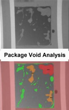
The X-Tek Revolutiuon is also equipped with software that does real time void analysis. BGA void analysis counts the number of voids, and determines the percentage of each ball area that consists of voids. The package void analysis function calculates the percentage the voids beneath ground terminations of bottom terminated components. The PTH (Plated Through Hole) fill analysis function allows for the analysis of fill level within plated through holes.


BGA X-ray Inspection Services - X-ray Analysis - BGA X-ray - 3D X-ray


